Baffles
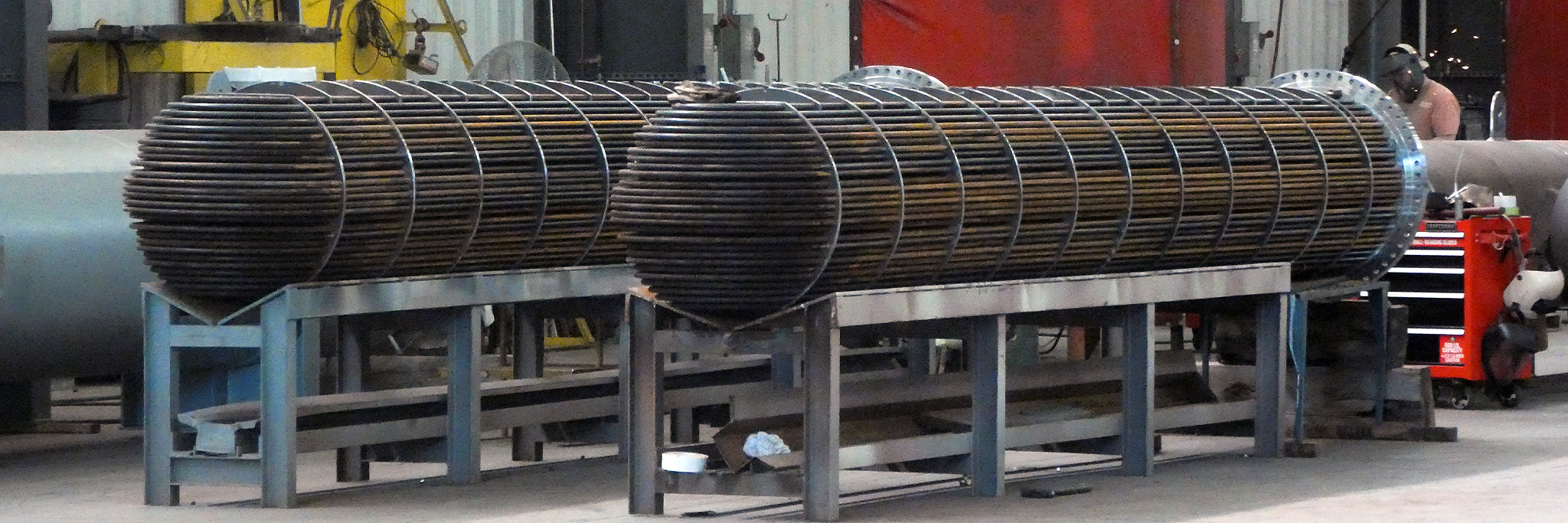
Baffles are the internal “guide” that directs the flow through the exchanger. The baffles directly affect the vibration, thermal efficiency, and pressure drop of the exchanger.
- Segmental Baffle – most common type with a standard baffle window
- Double Segmental Baffles – helps reduce pressure drop and lower velocity at the price of some thermal efficiency
- No Tubes in Window – less tubing in the baffle cut is good for very high shell side flows and lower tube side flow where vibration and pressure drop are a concern
- Helical Baffle – specialized design, good for turbulence and heavy fluids

As you move to more baffles, you help reduce pressure drop and lower vibration which also increases the sizes of the exchanger because of a reduction in thermal efficiency. The higher shell side flow, the more likely you are to need more baffling to reduce vibration and pressure drop concerns.
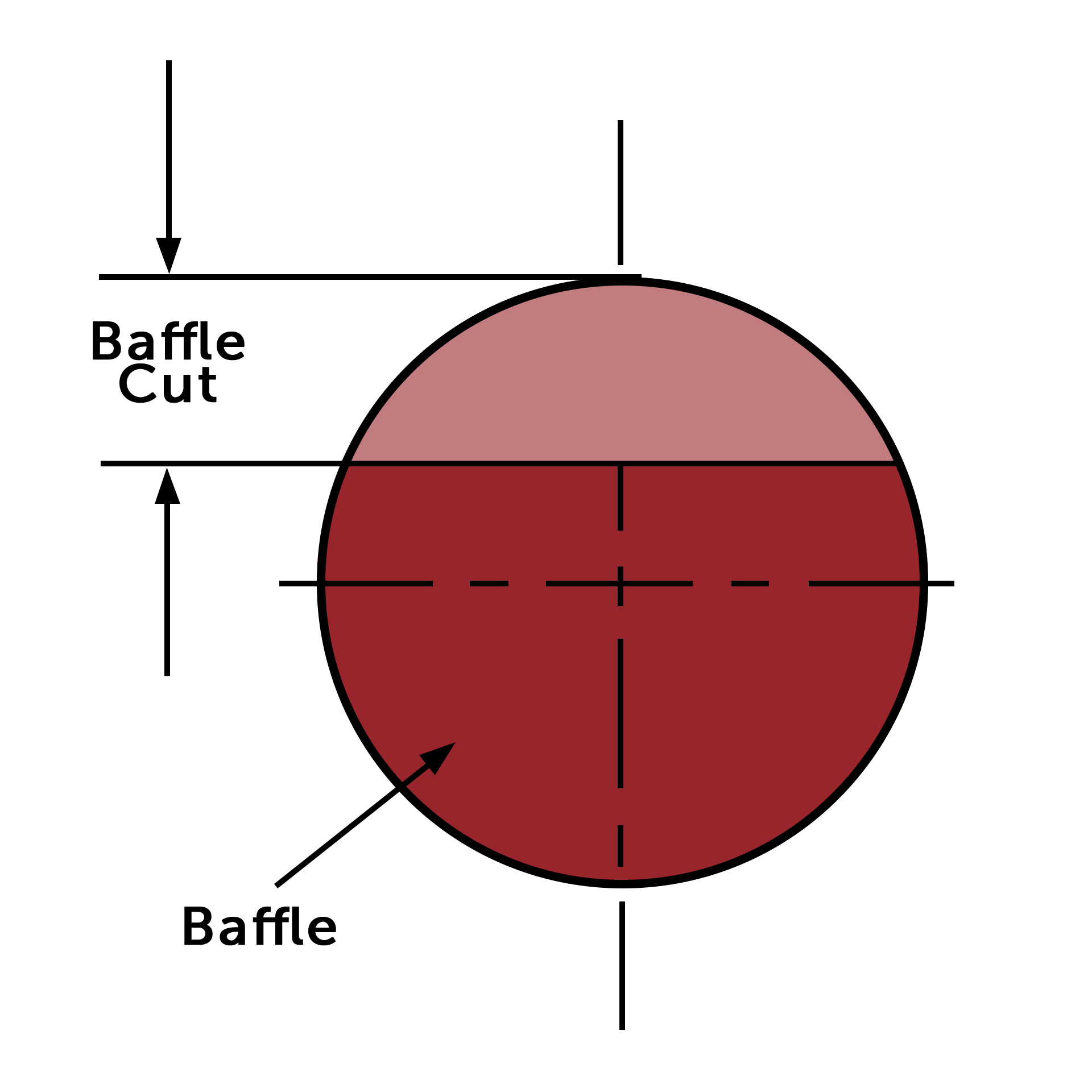
Baffle Cut
A Baffle Cut is the opening for the shell side fluid to pass through the exchanger.
- Baffle cut can vary between 10% and 45% of the shell inside diameter.
- Smaller baffle cut = high pressure drop but better efficiency.
- Large baffle cut leads to low vibration but also lower efficiency due to laminar flow.
- For best performance only baffle cuts between 20% and 40% are typical.
Tube Sizing
Tube Sizing refers to the OD or outside diameter of the tubing. Utilizing the correct tube size is both an art and science. Due to manufacturability, ¾” tubes tend to be the most economical for designing your exchanger. However, as flows increase larger tubes may be necessary handle the flow rates at normal pressure drops. Conversely, a smaller OD tube might allow you to push more tubes into the bundle to shrink the overall size (diameter) of the exchanger. As an example: if you size an exchanger with ¾” tubes but can use 5/8” tubes and shrink the unit by 2-4” in overall diameter, the savings will likely outweigh the easier manufacturability of the exchanger. All of these little nuances, are why it is important to have a thermal engineer with both an understanding of the thermal design AND capabilities of your manufacturing facility.
Tube Pitch
Tube pitch refers to the distance from center of tube to tube and the angle. There are four (4) common tube pitch designs. Triangular is the most common design and allows for the greatest thermal performance (the most tubes) in a single shell size. More tubes allows for more flow but can also cause more turbulence shell side leading to vibration and/or pressure drop concerns if too great. If maintenance is a concern, a square pitch is recommended to allow for greater space between the tubes.

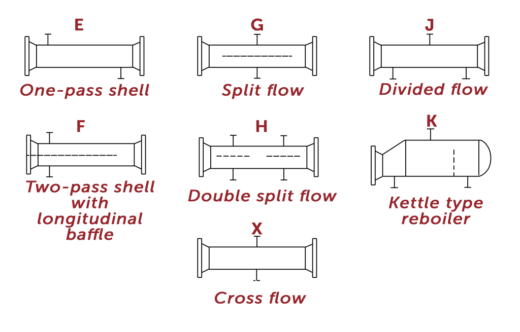
Shell Pass
Shell Pass refers to the inlet and outlet connections as well as the internal path of the shell side flows. The E, K, and F are the most common designs. As shell side flows increases, more connections are often need to avoid performance issues. This is where you might add a split flow path.
Other Technical Articles
As a leader in Slug Catcher design, here are some guidelines every engineer should know.
Choosing the type of Slug Catcher equipment for your next project? This breakdown will help guide your decision.
Understanding the separation methods for your finger-type slug catcher.
WHY US
Taylor Forge Engineered Systems
has continued the reputation of traditionally dependable products
to a variety of industries.
Integrity
We don’t compromise our practices and we won’t cut corners.


